Revit has some great tools to help us view a model from many different positions. We can have plans, ceiling plans, elevations, sections, 3d views or 3d sections. This enables us to view what we want when we want to see it.
I get lots of questions concerning the View Range in the View Properties. The View Range will allow you to change your Cut Plane and set your upper and lower limits. This is very helpful, but you need to understand one key rule: Revit will not actually show an item unless the view is cutting through that item.
A floor plan is typically a plan that is looking down and is cut by default 4'-6" above the level line. This means that a light fixture that is 8'-0" above the level line is not being cut by the cut line, which means that the light fixture will not be seen in the floor plan. One of the most common questions I get is "how do I get Revit to show the something on the ceiling on a floor plan?"
Here is a quick fix to be able to show light fixtures in your floor plan. Simply open the light fixture in the Family Editor, and draw a WHITE Model line from the fixture to the level line. This will cause the cutline to cut through the white model line and then show up on the floor plan. It should be white so it will not show up on the screen or on a plot.
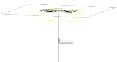
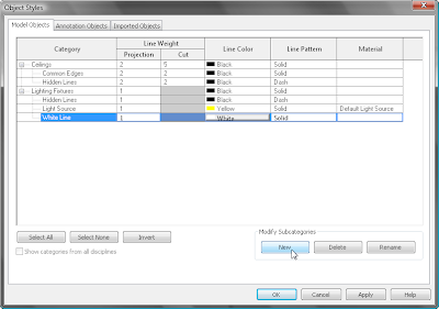
To create the Model line, it works best to draw it in an elevation view. Once it is drawn you will need to create a new subcatagory in the Object Styles under Light Fixtures and assign that catagory to use a white line.
Then you will need to change the line to be assigned to the new sub catagory.
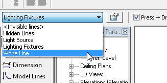
Load the light fixture back into your project and your light fixture now shows up in the floor plan. You may also want to override the graphics of the linework for the light fixture in the floor plan to be a hidden or dashed line.
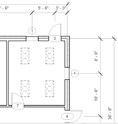
This is a quick and easy way to show items above that are not being cut by the cut plane.


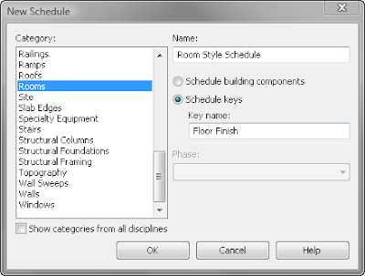
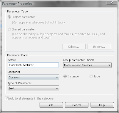
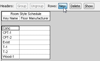
 The Split Face and the Paint tools allow us to split the surface of a wall and apply a different material to that portion of the wall.
 Inside the Advance Model Graphics Settings dialog box you can set the silhouette edges to any linetype you have in your project. This will automatically apply this linetype to the outside edges of your view.
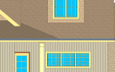
 Silhouette Edges set to Medium


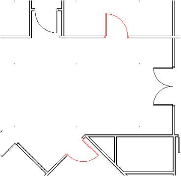



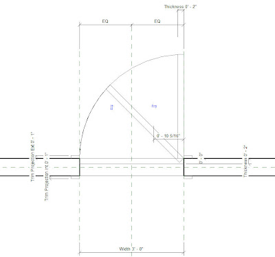
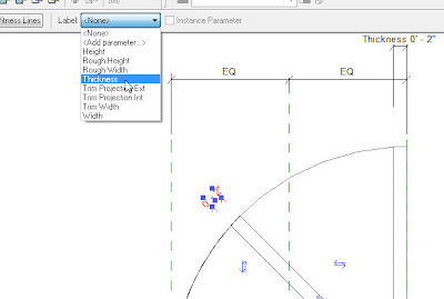
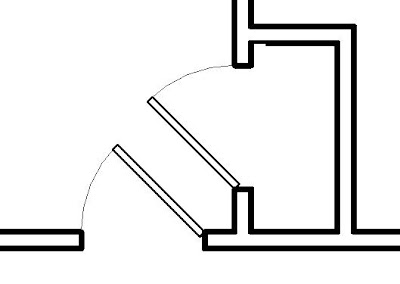
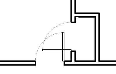 Modifying the plan swing of doors is a simple process, as long as you understand a few things. You will need to open the door family that you want to modify by highlighting the door in your project and then picking the Edit Family button on the Options bar.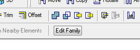



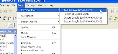
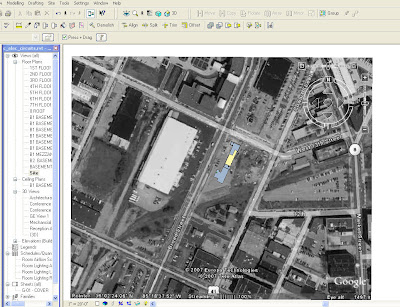 If you want to publish your 3D model into Google Earth, you will need to switch to a 3D view in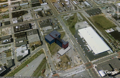


 The second button, Draw Points, will allow you to assign a spot grade at any point. You also use the Draw Split Lines button to split the surface of your floor or roof into multiple surfaces. This does not make your floor or roof into two elements, it just divides the surface.