Search This Blog

Wednesday, December 06, 2006

Revisions in Revit

The way Revit handles revisions works very well. I will walk you through the simple steps in managing revisions for a project.

The first step is to open the Revision Setting dialog box. Expand the Settings pulldown and select Revision to open the dialog box.


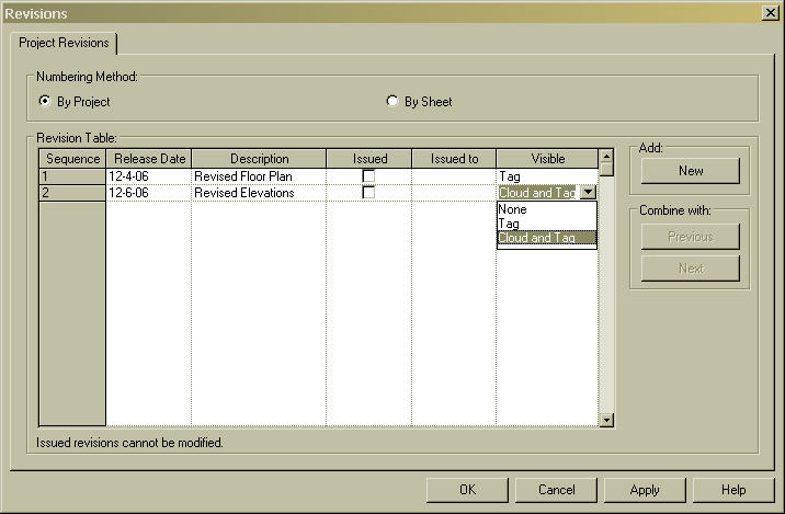
The first settings will control whether your revision numbers are By Project or By Sheet. This will depend on your company standards. By project will tag your revision with the delta symbol of the next available number. By sheet will tag your revision with the delta symbol of the next number of that particular sheet. You should set this at the beginning and leave it as your default.

The Revision Table begins with one revision as the default. You can edit the Release Date, Description, check the Issue box, or fill in who the revision was Issued To for any revision. You can add new revisions by clicking on the NEW button.

Once you have a revision issued, you may want to change the visibility so the contractor will not get confused by looking at old revision clouds. You can choose to show either "Cloud and Tag", "Tag", or "None" under the Visible column.


The actual Revision command can be found on the Drafting menu bar. This command is only available in a Sheet View. Once the command is started, you will enter into a sketch mode. Simply draw the cloud around the area that was revised and click Finish Sketch. You can then tag the cloud by starting the Tag command and picking By Category. If the Revision Tag is not loaded into your current project, it can be found under the Annotation folder in your family directory.

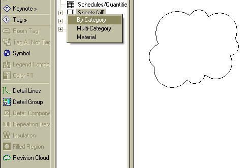
As soon as you place a cloud onto a sheet, the Revision Schedule in the title block will be updated to include the revision number, description, and date. The revision schedule is included on the default template title block.


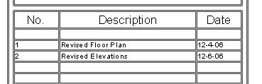
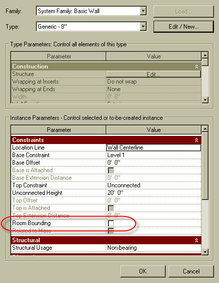
There is a known bug with release 9.1 that will not allow you to add a revision schedule to a custom title block. Hopefully this will be fixed soon, but for now, you can create your title block by editing the title block on the default template.

Keeping track of your revisions are simple in Revit. It manages all your revision numbers and dates. Of course, hopefully you will not need to know how to use this due to the fact that you never actually have to issue any revisions... right?!?

Friday, November 17, 2006

Making Spaces Work For You - In REVIT

It only makes sense that my first "How To" tip in Revit be on spaces. Especially since the current issue of AUGI World features an article by yours truly on Making Spaces Work For You in ADT.

Spaces in Revit are called Rooms. They work similarly to ADT with a few exceptions. Rooms in Revit define the use of the space. They are simple enough to define. You begin by clicking on Room on the Basic tab of the Design Bar. Then as you roll over your plan you will see the room limits highlighted by enclosed walls. On the Options bar you have the option to place the Room Tag as you are defining the rooms. You also have options to set the upper limits of the room, the rotation of the tag, and naming the room.


Once the rooms are defined, you have a couple of additional options to define the extents of each room. First, on the Room and Area tab of the design bar, you can use the Room Separation tool to draw lines to define the extents of the room. This is useful when you have an open area that is divided up into separate spaces. As you draw room separations, the rooms that are already defined will be updated to extend to the room separation lines. The area outside of the room separation line will not be part of any rooms. You can use the Room tool to define the new room that was created by the room separation tool. So like ADT, you can use either walls or lines to define the extents of your rooms.

You also have the ability to select on an individual wall and go into the properties to tell it not to use this particular wall as a room boundary. This will be useful when working on a restroom with toilet stalls. You will want to set the toilet partitions not to act as a room boundary. Simply uncheck the box in the options dialog box next to Room Bounding. If you make this change after the spaces are created you will get a warning dialog box because you will have two spaces that will be overlapping each other. In the warning dialog box click on Delete Rooms and one room will be deleted, leaving the new combined room.


Rooms can be used to create schedules like square footage schedules or room finish schedules. You can also use Color Fills to create a colored floor plan for a graphical representation of the room extents.

Rooms are similar to Spaces in ADT. They contain the information of the Room. With rooms you can define usage, finish materials, calculate square footage or volume information, or simply use them to insert your room tags.

Wednesday, November 08, 2006

Move over ADT... Make room for Revit

I have had some time this week to dive deep into Revit. I was hesitant in the beginning like many are, but I just finished my first project. As an ADT user for years, I found Revit fairly easy to pick up as long as I kept one thought in mind-- forget what you know about CAD. I know that goes against the name of this blog, but it is necessary to understand how Revit works. I have been promising people that I would extend this blog to include Revit, and now is the time.

The basic commands in Revit work similarly to ADT. The walls clean up when joined, doors and windows can be inserted into walls, and there is a line command that you can use by picking a start point and an end point. That, however, is where the similarities end.

I was serious when I said to forget what you know about CAD. I forced myself to do this as I was learning this program. When I caught myself trying to do something in the way I would in ADT, I quickly became frustrated. I believe if I had never learned ADT, I would have been able to pick Revit up without a hitch. Once I got into it, I started enjoying it more and more. Looking back at my first project, although it was small, I can see how you can make design decisions at an early stage and see the effects of that decision in multiple views.

In the past I have had the attitude of, "well, ADT can do that too." Yes, ADT can do much of what Revit does. But you have to work to make it do it. The coordination of drawings, or views as Revit calls them, is what impressed me the most. I never had to worry about updating xrefs or schedules, or about making sure that I had the right callout on my elevations.

I do not want to run any of my ADT users away. I will continue writing about ADT, but expect to see me writing more and more about Revit.

Below are several images of my first Revit project. I am impressed, even if nobody else is.


Thursday, October 19, 2006

Successful CAD Camp

Alacad hosted CAD Camp in Birmingham this week. I hope the ones that attended walked away with a greater knowledge of AutoDesk products. I feel like it was a huge success, but being on the presenting side of the table sometimes muddies the water. I presented two classes, both ADT related-- one on Spaces and the other on AEC Dimensions. Both classes received good feedback. If you were not able to attend, be sure to check out the next issue of AUGI World. You will find an article of mine on Spaces.

I also sat in on a Product Migration Roundtable hosted by Robert Green. This was a useful discussion of how to get new products implemented inside of your company. Robert did a good job on leading the discussion about what we have seen work, and what has not worked in implementation. I recently returned from Chicago where I attended ICE (Implementation Certified Expert) training. I will be sharing some of the information that I learned in the next few weeks here in my blog. The training class was intense, but I was able to pass the test to certify me as an expert. Without getting into too many details for now, just keep in mind that implementation does not equal training. Training is only a small part of a successful implementation. Watch for more information on implementation in coming blogs.

By the way... we will be hosting another CAD camp in Nashville on January 18, 2007. Watch this link AUGI CAD Camp for registration info to be posted soon.

Wednesday, September 27, 2006

ADT SP1 is Available!

SP1 for ADT 2007 has been posted. I am in the process of installing it now. I've read the readme file, and it looks like it has corrected many of the little bugs inside the program. Here is the link to download the service patch. ADT SP1

Monday, September 25, 2006

A.U. Connect

Autodesk University is coming! I am excited about this year's A.U. I am all signed up and ready to go to this great event. My excitement grew this week as the A.U. website launched A.U. Connect. This is a great place to see who is coming and who is similar to your personality and likes. If you haven't registered yet for A.U., get with it and sign up. The classes are filling up fast. If you are registered, then log into A.U. connect and enter your profile information. It is fun to see who is similar to you and where they are from.

Wednesday, September 06, 2006

Using Lists in ADT 2007

One of the most unnoticed features in 2007 is the ability to create lists. These lists can be used to help your CADD standards. As an ex-CADD manager, I despised reviewing a set of drawings when I found the same term used over and over, but with different call outs. For example, calling out Gypsum Board in one set of drawings, I found it listed as gyp. bd, GYP. Board, Gypsum, US Gyp, Drywall, and of course, gypsum board. Calling out the same material with so many terms will lead the contractor to confusion or R.F.I.'s. The ability to create lists will enable your users to pick from a pulldown menu the name of the material so it is coordinated and never misspelled.

To create a list, go to Style Manager. You will see List Definitions under Multi-Purpose Objects. You can create a new one or modify an existing one. They are styles, and like every other style, they must be loaded into your current drawing to be used. In creating a list definition, there are two main tabs that need to be looked at. The Applies To tab is critical to assign what this list will be used for. You will see three(3) options listed: Manual Property Definition, Space Names, and Zone Names.

Manual Property Definition should be selected if you intend to use this list on any property set definition. Once this is selected, you have the option to change the type of a manual property set definition from Text to List in the Definition tab of the property set. The following example has a list created and assigned to the door frame material. The list gives the users the option to pick metal, wood, or aluminum.

The other two Applies To options in the List definitions will enable the list to be used as either Space Names or Zone Names. This is a great way to ensure that Room Names are spelled correctly. To have your room tag pull the name from the space name, set this up on your MV room tag block. To use this list as space names you need to assign the Space Names of the space style to the list in the Design tab of the space style.

This example shows a residential list of space names that the room tag is pulling from to name the room.The Items tab in the list definitions is where you actually create the lists. It is fairly straight forward. Simply pick Add and type in the name of the item.

Lists can be created in templates so they are always loaded into your current drawings. Being able to pick a list, as opposed to typing it in, will increase productivity and decrease inconsistency and spelling mistakes.

Thursday, August 31, 2006

Publicity

I want to thank those who recently blogged about my site. I appreciate the kind words. I am aware of the following bloggers that have mentioned this site.

A big thanks goes out to JTB World Blog, Beside the Cursor..., and RobiNZ CAD Blog for the recent publicity!

Friday, August 25, 2006

Out of the Box Property Sets

Property sets are like place holders for data that can be used to analyze your project. You can create any property set you need in Style Manager. ADT comes with several property sets out of the box, but they are not loaded automatically. Some of them will load when you insert a schedule or a tag. I was trying to set up a template, and I wanted to customize the property sets in the template. I had trouble figuring out a way to get the property sets loaded. I came up with a short cut to get all the "out of the box" property sets loaded into your current drawing.

On the documentation tool palette, copy and paste an existing tag tool. It does not matter which one-- I used the door tag tool. Rename your copied tag tool "Property Sets." Right click and go into the properties. Inside properties, change the type to "Property Set Data".

Then click on the icon in the property data box to open up the Add Property Sets dialog box. Select all and pick OK.

When this tool is used in your drawing, it will load all the available property sets. This is a great tip for CADD Managers who are trying to set up their templates. You can load all the property sets, customize them to meet your company needs, and save it as your template. When users insert schedules and/or tags, the property sets that work with that schedule and/or tag will already be loaded into their drawing. If the property set already exists in the drawing, this ensures they are using the company standard property set.

Tuesday, August 22, 2006

Layer Key Overrides

ADT does a great job of placing objects on the correct layer. As I am drawing, I rarely look at the layers that the program is placing items on. It puts walls on a wall layer, doors on a door layer, etc...

But what happens when I need to put a wall on a wall-demo layer? Hmmm... Do I have to manually create that layer and use the change properties to change it? If you don't know about the Layer Key Overrides, then you are probably doing that manually.


ADT has a built in tool that few users are taking advantage of. The Layer Key overrides will allow you to temporarily override the layer that the objects are placed on. If I need to draw a wall on a wall-demo layer, all I have to do is to turn the layer key override on and set the status to Demo. As long as it is on, any object that I place will be put on a layer with a -demo extension to it. If I place a door, it will be put on a door-demo layer.


When I am finished drawing demo items, I simply turn the layer key override off and it's back to normal.


Layer Key Overrides - what a time saver. If you are not using them, check it out!

Tuesday, August 01, 2006

CAD Camp!

I am excited to announce that registration is open for this year's CAD Camp in Birmingham. It was just last October that I went to my first CAD Camp. What an experience!

I have to tell you a short story about my experience last year. I attended with two co-workers from my previous company. We drove down from Chattanooga, and as we drove, we were all talking about what we were expecting to learn from the day ahead. We were attending the opening keynote address, and I leaned over to my co-worker and told her that every time I attended one of these events, I was jealous of the speakers. I mentioned that I wanted to be up there presenting. She chuckled and we went on to our first training course.

This year I won't have to be jealous of the speakers. I will be teaching two classes with my co-worker, Alice Craig. I hope that you will plan to attend. Early registration is ongoing, just click on this link: CAD Camp. See you there!

Tuesday, July 25, 2006

Walls With Footings

While teaching an ADT class today, I was asked what is the best way to draw spread footings using ADT. My first thought was to use slabs, and size them accordingly. But after looking at it more closely when I got back to my hotel, I believe the easiest way to draw spread footings is with the wall command.

There are several wall styles that ship with ADT that indicate a footing below the baseline of the wall. They are located in the wall style drawings in the content folder. The settings are able to be edited through style manager. You can adjust the components to the desired widths and use the offset options to reach the required depth. The styles that ship with ADT have a component that is called footing, that has the concrete material applied to it, and it is drawn on a footing layer that has a hidden linetype. This is a quick and easy way to indicate footings below structural walls.

Below is a CMU-12 Concrete-12x24-footing wall style that shows the footing below as a hidden line. The components do show up well when you cut a section through it. If you simply need a footing without a wall, you can copy the wall style and delete the cmu component in style manager. This should help when you are trying to indicate footings below walls.


Thursday, July 06, 2006

System Requirements

A common question we get on a daily basis is, "What are the system requirements if I upgrade my current release of Autocad?" I have added some new links on the side of this page to direct people to Autodesk's recommended system requirements for each BSD product.

The two most important items to look at are RAM and your graphic card. I would not recommend anything less than 2 GB of RAM for the 2007 products. The graphic card should be a tested and approved card by Autodesk. The 2007 products have a built in optimizer to help configure your 2007 product to work more efficiently with your graphic card. Here is an additional link to see what cards have been tested. Graphic Hardware List.

Friday, June 23, 2006

The State of the Architectural World

After attending two State AIA conventions, I believe I have a better understanding of where architecture firms are coming from these days. I had the opportunity to meet hundreds of people from both the Alabama AIA Conference and the Mississippi AIA Conference. Both conferences were first class with excellent hotels, conference centers, and a large pool of national speakers.

As I talked to people at each event, I saw that the majority of the firms are not current on their release of AutoCAD. I am not one to suggest upgrading as soon as a new release hits the shelves just for the sake of upgrading, but I do evaluate each release to see if there are enough new features to make it worthwhile. Many of the firms that I spoke with are currently using release 2004, and were unaware Autodesk is in the process of retiring this release. If you are one of those firms, you should contact Alacad for an upgrade quote before the prices increase.

I was also not surprised to find many firms own Architectural Desktop, but are using it like AutoCAD. I heard many excuses as to why they are not using the ADT features. The main things I heard over and over again were that they do not need 3D, or it just doesn't work well to produce construction documents. Well, after listening to these reasons, I think it all can be summed up in two words - NO TRAINING. There are many advantages to ADT that can be used to increase your production in a 2D world. Autodesk is currently featuring a series of web casts on this very topic. Check out Amy's webcast if you fall into this category. Watch Amy's Screencasts

I did find several firms that are leading the troops into the world of BIM. I applaud them for their willingness to step out onto the cutting edge. Of the success stories that I heard, they all claimed that they would never go back to plain AutoCAD. This says much for the advantages. Will there be problems? Will there be times when you just don't get it? Will your production decrease on the first several projects? The answer to all of these questions is yes, but after the bumps clear out there is a huge increase of productivity. More importantly, however, is the assurance you will have that your documents are coordinated. When using a BIM (either Revit or ADT) your callouts will be correct, your schedules will match your plans, and your plans will match your elevations.

So I propose two challenges for the firms of Alabama and Mississippi. First, stay reasonably current with your release. If your release is 2004 or older, then upgrade now before it costs you more money. Second, if you are a proud owner of ADT but you are still using it as AutoCAD, get the training necessary to use the ADT features.

Monday, June 19, 2006

Creating Your Own Schedule Tags

Putting tags into your drawings can be monotonous. If you are trying to number each one, it is sometimes hard to keep the numbers correct so you do not have any duplicates. ADT can assist you in this area by using schedule tags. Many tags come with the program that can be used for room names/numbers, door numbers, window types, and wall types. But because these "out of the box" tags do not match specific companies' standards, many people continue to use the old block with an attribute method. This costs time and money. The schedule tags in ADT can automatically number and be added to a schedule for additional analysis.

Schedule tags are actually very easy to create. I will demonstrate here how you can use your existing tags to create ADT schedule tags that can be assigned to property sets.

1. Begin with your block. Let's imagine I have an equipment tag my company uses that is made of a simple circle with a letter in it. I simply pick the "Define Schedule Tag" command from the "Format" pulldown menu.


2. I select the existing block as my object to create tag from. It opens up a dialog box showing my block in the preview box. I can then give my new schedule tag a name by typing it in the name box.

3. It will automatically list my attribute as a label in the lower part of the dialog box. To convert this text to a property text that can automatically be filled in and scheduled, I change the type from "Text" to "Property".


4. I select the property set that I want to assign it to, and assign a property definition. In this example, I am working with my company's equipment block so I picked "EquipmentObjects" as the property set.


5. Finally, pick "Number" as the property definition. Select "OK" to finish.


I can now use this schedule tag to schedule plain blocks in my drawings for equipment. It will automatically number each piece as I insert the tags. I can also create a schedule that will look for all my tags in the drawing and schedule them for me.

Using this simple process to create your own schedule tags enables you to have all your company standard tags converted into schedule tags in no time.

Monday, June 12, 2006

Investigating Your Layers


Even though the new layer tools located on the Layer II toolbar in 2007 have been around for awhile in Express Tools, I have never used the LayerWalk tool. The LayerWalk tool is a useful command to help you determine what is on a certain layer. When the dialog box first opens it highlights all the layers that are currently on. You can then pick on a layer name in the dialog box, and your drawing screen will display only the items on that layer. This is a quick and easy way to begin working with a new drawing that has been sent to you to analyze. As in most dialog boxes, you can hold the "Ctrl key" down to select multiple layers. If you are just browsing, you can leave the box checked on "Restore on exit" and your drawing will return to the layer state it was in prior to starting the command. What a great investigating tool. Give it a try!

Thursday, May 25, 2006

Last Minute Changes

Making last minute modifications to your floor plan can be risky, but we all do it. We think we have everything worked out, then we realize we need to move a wall to make room for an additional chase that our MEP engineer is asking for. We think to ourselves, "No problem. This should be a five minute change." We use the stretch command and instantly it's finished. Our drawings are printed, stamped, and sent to the architect of record for signature. We lean back in our chair sipping a cup of coffee thinking how glad we are to have that project out the door. Then it happens... we get the dreaded roll of drawings back covered in blood. We wonder just how many red pens were actually used to create so many redlines. Your first thought is, "what in the world could be so wrong with my perfect set of documents?"

If this scenario has ever happened to you, then you were probably not using the Autodesk products to their full advantage. Last minute changes are where BIM (Building Information Modeling) products like ADT and Revit shine. If your documents had been tied to a single model, then your ceiling plan, enlarged plans, interior elevations, sections, life safety plans, square footage tables and other details that were affected would also have been changed. We are all human, we make mistakes. In last minute changes, we tend to forget what a simple change can effect.

BIM makes so much sense to use, but as architects we think its too hard to learn, or that the way we produce our documents has worked for years-- why change what works. Change is always hard, but change will push your firm to a level above your competitors. We know in the long run it would be better if we could take advantage of all the features in ADT, but we throw our hands up claiming it doesn't work right or that it would take too long to produce. Well, it might take a little longer the first few times, but once you understand how to do it you will never go back.

Alacad offers several classes to help you gain this knowledge. We also offer what we call "over the shoulder" training. In this case, we work with you while you are working on a billable project to teach you how to use these techniques. If you are struggling with changing your old habits, or you think its too complicated, give us a call and let us assist you.

Thursday, May 11, 2006

Two Weeks of Mondays

2100 miles and two weeks into our Autodesk 2007 product launch, I find myself having trouble remembering what town I will be in when I wake up in the morning. It’s like being in the movie Groundhog Day, except I am in a different hotel each time. This has been a very successful two weeks, however. Yes, we are worn out, tired of sleeping in a different bed every night, having to eat out every meal, and waking up at the crack of dawn to set up for our presentations... but I have met some great people and I believe that people are getting excited about the new 2007 products.

Tomorrow we will be presenting for Huntsville. Next week I get a vacation (sort of). I am baling on my co-workers to take my lovely family to Florida for a week of Mickey Mouse. I am not sure if you can consider Disney World an actual vacation. I am sure by the end of it I will be more tired than I am now, but it will be fun to spend the week with them and not have to sleep alone. Then the week after Disney, I get to finish the 2007 Launch tour with my family, as we hit the Gulf Coast towns.

My schedule is filling up fast for the following month. Many customers want us to come to their firms, either to discuss the new products in more detail or to help them plan their implementation process. But for now I still have several more Mondays to go.

Tuesday, May 09, 2006

Kudos to My Dirt Mover Buddy

I wanted to give a big thank you to my co-worker for his previous weak moment when he blogged about my blog and my expertise.

Welcome to all the dirt movers that have made their way from the dark side to the wonderful world of architecture. I hope you enjoy my blog.

To return the favor, please check out his blog at http://www.beneaththelines.blogspot.com/.
I am not sure that my debt to him will be considered paid due to the fact that I am sure he will not get near as many referrals from my site as I am getting from his site.

Thanks Jason for the nice blog.

PDF Vs. DWF (Part II)

A couple of posts ago, I wrote about how excited I was to see the new plot to pdf feature in the AutoCAD 2007 based products. I am still excited about this because I know people have been screaming for this feature for a long time. Well the battle is not finished. I now want to write about how excited I am about the new dwf underlay feature. Not that I want to retract my previous blog, but I want to make sure everybody understands what the dwf underlay feature means to us as a profession.

Have you ever sent a consultant a drawing to use as a background (I know I have.) When you send somebody a .dwg file, what keeps that person from making changes to it without your knowledge. I have worked with engineers previously that were very reluctant to send me their HVAC drawing for the fear that I might make changes to it. (If they only could understand that if I actually did change it, it would only lead to future RFI's or Change Orders).

The new dwf underlay feature will allow us to send secure drawing files to consultants without them being able to change or edit the drawing. Previously, when I sent a DWF, they could view it, or plot it, but they could not actually use it in their drawings. The same goes for a pdf file. You can not insert a pdf file into your drawings. Now we can insert a dwf as an underlay, similar to an xref, and use it as a background. We can even use our AutoCAD snaps to snap to points on the dwf. The is wicked cool. (as Matt Murphy would say).

In my opinion this gives dwf's a whole new light. So the battle continues.

Thursday, May 04, 2006

Adding Blocks to Schedules

Door elevations are fairly typical on most projects. So typical, that we tend to not care if we have elevations that we stole from other projects, and one or several of those stolen elevations do not apply to our project. This can lead to confusion for our poor contractor. I have inserted a standard door elevation block numerous times on my jobs and never even thought to double check to see if they are all actually being used. This can lead to RFI’s, and even change orders, if they do not match the door schedule.

ADT 2007 has introduced the ability to insert blocks into schedules. With this we can tie the door elevation blocks to our door objects in our plan, which insures that they match both our plan and our door schedules. This is a simple process that could lead to less RFI’s and/or change orders.

To the left is a sample schedule, that I created in ADT 2007, that is using standard blocks as the elevations. They are fairly simple to create, and once they are created you can use them over and over again on your projects. You can assign a tag property set to the door to indicate the type, and have that tag be listed in the door schedule. If all the doors of one type are deleted from your plan, then the door elevation schedule will update to reflect that change by removing it from the schedule. One downside of this new feature is that you can not use the door objects in ADT to generate the door elevations. You have to use existing blocks or simply draw the elevation using lines and save it as a block. (Maybe that will be in 2008.)

Friday, April 28, 2006

Ready or Not, Here We Come!

As I begin this last day of preparation for Alacad's 2007 product launch, I realize how excited I am about beginning this 14 city road show. The Alacad team will be traveling next week to Jackson, Memphis, Birmingham, and Montgomery. While I go over the product presentations, and proofread my power point slides, I can't help but think about the diversity of firms that I will come into contact with.

You see, this product launch is not just to demo the 2007 product line for me. I see this as an opportunity to meet people from the leading firms in the southeast region. I can't wait to talk to you, to hear your success stories, your questions, and yes, even your complaints. I am curious to see how you are currently using the Autodesk products. I want to find out what's working and what's not working. I want to be able to share with you strategies that work to get your company to that next level.

This time of year for many is all about the new release of AutoCAD. I see it as a new chance to get to know the leading CAD users in my industry. So I'll be looking for you in a city nearby soon. See http://www.alacad.com/events.html for the complete schedule.

Tuesday, April 25, 2006

Real Estate Is Going Up

How many remember the DOS days? Autocad running on DOS. That infamous file menu on the right side of the screen. When the Windows version was released, we all went kicking and screaming without a choice. When we got there, we could hardly see our drawing screen due to all those toolbar buttons. Once we got use to the buttons, we all got toolbar happy. Creating toolbars for all our favorite commands and lisp routines. Then Autodesk introduced pallettes. What a neat tool. But boy, they take up a lot of screen space! Some switched to duel monitors, and some learned how to zoom and pan extremely often.

Well, Autodesk has heard our grumblings. In the 2006 and 2007 releases they have introduced Dynamic Input. This setting is down on your status line as simply DYN, and will enable you to free up some of that precious real estate on your screen. When you first turn it on, you might say to yourself, "what in the world is all that junk on my screen." But before you wipe it all out by turning it off... look at it... it's the command line information in your drawing area.

With the use of Dynamic Input, you can turn off or at least collapse your command line and the screen instantly gets larger. You might be thinking that you need it at first, and thats fine. With the auto collapse capability, you can wean the command line way slowly. Below I have the command line both minimized and expanded, but it still takes up less space.


This not only saves you screen space, but it will also enable you to keep your eyes focused on your crosshairs. No more looking up and down.. back and forth from your command line to your crosshairs. With the Dynamic Input prompting you next to your crosshairs, your eyes can stay focused on your drawing.

To try this feature out you can simply click the DYN button on the status bar at the bottom of the screen. Right click on it and go into the settings to make sure all the check boxes are checked as you see here to the left.

Take back that screen. No, we can't go back to DOS, and really, we don't even want to. But we can advance forward with the new features and tools without the command line taking up our screen space.

Tuesday, April 18, 2006

A 2007 Hidden Secret

I believe that the most appreciated little secret in the 2007 release will not be the improvements on the walls, AEC Dimensions, the ability to create custom stairs from linework, or the one click space creation with room tags. There is one feature that has not been discussed very much. I bet most of my readers have not heard about it. In my mind it goes against what Autodesk has been pushing on us for the last several years.

All right. Enough already. The little known feature is the improvement to electronic plotting. Autodesk e-plot format is the dwf. With the download of the dwf viewer, one can view AutoCAD drawings without having AutoCAD installed. The ability to view 3D dwf's was added in release 2006. With this, one might think they were trying to monolopize the market on electronic files.

As neat as the dwf is, users for some reason or another kept trying to figure out the best way not to create dwf's but pdf's. It has almost been like a small battle between dwf's and pdf's. But to my amazement, Autodesk has added the ability to create pdf's inside of AutoCAD.

There is a new "dwg to pdf.pc3" file that comes with AutoCAD 2007. No more having to purchase Adobe Writer or some other knock off program to create pdfs within AutoCAD. I think most users will appreciate this more then Autodesk knows.

So where does this position Autodesk in the dwf vs. pdf battle? We will have to wait and see. But while we are waiting, I am going to enjoy the new plot to pdf feature.

Friday, April 14, 2006

Texas In My Rearview Mirror….

As I fly back from a week long trip in Dallas, Texas for Autodesk Bootcamp, I am asking myself if the main question I had going into this training event was answered. I think I need to wipe the fog off of my mirror to determine if I got a clear answer.

Autodesk has strategically positioned themselves so that their main competitor in the Building Solutions Division is themselves. With the advancement of both Architectural Desktop and Revit, it leaves an architect with questions as to which solution is right for them. Now with the introduction of Revit Systems competing with Autodesk Building Solutions the MEP field is questioning which way they need to advance as well.

Coming into this week I was hoping to leave with a clear definition as to which product I should recommend for my customers. I do have a better understanding, but it is not as clear as I was hoping. I do feel confident that Autodesk is not going to abandon either product anytime soon. So either product will lead a company to long term advancements.

The marketing for Architectural Desktop (ADT) is selling the product as the AutoCAD for Architects. This program is meant to give Architects the tools they need to complete their projects better and faster using the AutoCAD platform that they have been using for years. As an ADT guru I tried to go into this week with an open mind to both products. ADT has made several key improvements in the AEC Dimensions and Walls and Scheduling areas that were long awaited. With these improvements I believe that architects can finally begin to use them the way they were intended.

Revit is now on version 9 and FINALLY has a real way to create 2D details other than importing in their AutoCAD details. (YEA!!!) The Revit platform is marketing themselves as the Building Information Model for architects. This program is meant to operate the way architects think. I tend to agree that this platform has some great tools to assist the architect in completing their projects. The fact that you are working on one model and any changes made are instantly made through out the project is a huge benefit for Revit.

Over the last several years, the Architectural industry has begun a transformation from Architects directing drafters to complete the drawings to Architects completing the drawings themselves. The position of a “drafter” in an architectural firm is vanishing. Architects need to have a good understanding of what they are drawing when they are drawing. No more drawing bogus lines and simply calling them out in schedules and notes. Now you are drawing with object based technology. As you create these drawings, you cannot simply draw an interior partition wall. You need to know if it is fire rated, structural, 8'-6" high, or does it extend to the structure above?

After talking with other resellers this week, I found that this country is split on both ends as to which product is applicable. Both the East coast and the West cost have jumped on the Revit band wagon, while the central part of the U.S. are die hard ADT users.

I believe it is a case by case determination as to which product is right for each firm. The one marketing strategy that has changed from previous years is that Autodesk is not pushing either product more than the other. This along with the amount of dollars being pumped into the development of ADT informs me that ADT is here to stay.

So if you are as confused as I am as to which product is right for you don’t feel bad. Let me leave you with a quote that hit home with me this week. “What is truly innovative today will be ordinary tomorrow.” AutoCAD was once an innovative software, but is considered ordinary today. Both ADT and Revit are innovative today. Don’t let your firm be considered ordinary tomorrow. If you are not taking advantage of one of these vertical products you will be left behind in technology. Take your firm to the next level by implementing one of these products.

Wednesday, April 12, 2006

Hut Two, Three, Four....

My first Bootcamp was not exactly what you might be thinking. I am currently writing this on my last night of a long, exhausting week of technical training for the new 2007 product line for Autodesk. Although we did not wake up the sound of a bugle playing and we did not have to do push ups, I am extremely worn out.

My expectations for this week of learning about the new versions were high. I never dreamed that it would be so intense. With 6 product lines in the Building Solutions Division it has been non-stop learning. I really look forward to being able to share with you all the things you don't know about the new version.

ADT, ABS, ARB, ARS, ARS Series +, and of course ACAD are a lot of acronyms. I am not even sure if I know what they all mean. But these are the products being offered to the Building Solutions Division to help us realize our ideas. Whether its AutoCAD for Architects or a better AutoCAD for MEP engineers or a total Building Information Model for both Architects and Engineers, 2007 has what we need to know. Below is a link to all the new products to get a closer look.

New Building Products Include:

I look forward to Alacad's product launch beginning in May. Check out www.alacad.com for dates and times in a City near you. My co-worker and I will be doing a whirl wind tour presenting all the product lines.

Tuesday, April 11, 2006

Welcome to my first Blog

I was encouraged by a co-worker to begin this blog. This is a new experience for me. I hope that I am able to help architects and engineers become more knowlegable about what they don't know about the vertical product lines for the Building Solutions for Autodesk.

As this is my first post in my first blog, I will keep it short. I am excited to share my experience with the readers.