Search This Blog

Wednesday, April 25, 2007

Sloped Floors and Roofs in Revit - A Great Addition

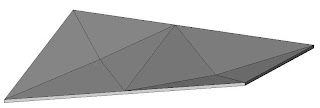
The Revit Development Team put in a last minute addition to Revit Architecture 2008. It did not show up in any of the Beta’s, nor has it been mentioned in any of the marketing, but it is one of the better enhancements to the program. Have you ever tried to create a sloped floor or a flat roof with slopes? What a pain it used to be. Now in 2008 it is a breeze. This works both on floors and roofs (with no defining edges.)

Place a floor or roof as you normally do. Once the floor or roof is drawn, if you reselect it, you will see a new set of tools on the Option Bar. These tools were taken from the Revit Structure program. In Revit Structure they use these tools on slabs. Now thanks to this last minute add, we can use them on floors and roofs.


When selecting the first one, Modify Sub-Elements, you will see a green line outlining your floor or roof, and green grips on each corner. You can move the entire edge or individual corners up or down. You can also create warped slabs by moving corners in opposite directions.


The second button, Draw Points, will allow you to assign a spot grade at any point. You also use the Draw Split Lines button to split the surface of your floor or roof into multiple surfaces. This does not make your floor or roof into two elements, it just divides the surface.

These tools are great, but I can already think of two additions that would make it even better. I would like a way to type in a slope angle or percentage. I would also want to be able to label the spot points with a tag that would call out the elevation. Currently these options are not available. Put these on your wish list. I guess they have to leave something for the next release.

Friday, April 13, 2007

Happy Anniversary

It's hard to believe that it has been a year. It was one year ago, that I was convinced by my co-worker, Jason Hickey, to start a blog. Looking back, I feel that it has been successful. I never thought it would take off, but here we are a year later getting 200-500 hits a day. I hope to continue to provide useful information to my AEC readers.

Thank You for reading!

A Dashboard that Might Get Used in 2008

The Dashboard was introduced in AutoCAD 2007. It was a new palette that few people found a use for. It had all kinds of 3D rendering/visualization tools on it, but unless you were working on a rendering, you probably turned it off. I would even go as far as to say that most people probably turned it off the first time they launched 2007 and never turned it back on. I mean, why would you when you already have your favorite toolbars and tool palettes? It was just something that took up valuable screen space.

Let me introduce you to the new and improved 2008 Dashboard. This one might make the cut when users launch 2008 for the first time, if they understand that it is now CUSTOMIZABLE! That's right, it is totally customizable. You can add or delete what you want. You can put all your favorite commands in one spot and completely turn off all those toolbar buttons.

The out of the box dashboard comes with several predefined Control Panels that have various tools on them. If you right click, you can select which ones you want by picking Control Panel and then checking the ones you want on. You can also right click on a panel that is currently on, and select Hide to turn it off.


I would start by browsing through these, turning off the ones you do not like, and leaving the ones you do like. Here is a sample of my favorite ones.

You can also go into the CUI by right clicking on the dashboard and selecting Customize Commands. Once inside the CUI, there is a new category for the Dashboard. Here you can add new panels and simply drag and drop your favorite commands onto the newly created panel.


With these added enhancements to the Dashboard, I can visualize everyone dashing off to customize their dashboard ( I know it's corny, but it could happen!)

Wednesday, April 11, 2007

Hiding Elements in Revit 2008

Yesterday I was asked by one of my customers how to hide individual elements or families in a view. I told him that until he installs Revit 2008, he would have to create a view filter in Visual Graphics and turn the visibility off for that filter. He asked what was different in 2008, so I am going to describe one of the new features here.

Hiding elements in Revit Architecture 2008 has some new features. The temporary hide feature in previous releases was just that-- temporary. When an element was hidden using the
Temporary Hide tool, it would only be for that session. So, when a view with hidden elements was printed, all elements (whether hidden or not) would plot.

Let me introduce you to the
new Persistent Hide tool. This will allow you to hide either individual elements or categories that will remain hidden and not plot. Prior to this tool, we would have to create some sort of view filter to hide elements.

This tool works by selecting the element that you want to hide
in the view, right clicking and picking Hide In View. You can select either Elements or Category.

Once the element is hidden, you can select on the new Reveal Hidden Elements icon (the light bulb) on the View Control Bar at the bottom of the screen. When this is selected, all non-hidden elements will turn gray and you will get a bold magenta outline around your view to indicate that you are in a view hidden elements mode. Your hidden elements will be magenta as well. If you right click on a hidden element, you can select Unhide In View to unhide the element.


You can also turn temporary hidden elements into persistent hidden elements by selecting the element and picking on the Temporary Hide/Isolate icon (the sunglasses) on the View Control Bar. You will see a new option on the menu to Apply Hide/Isolate to View.


With the new Persistent Hide feature you can see what you want, and hide what you don't want to see and plot it that way. Hmmm... it actually works the way you want it to.

Vista Patch for AutoCAD 2007

If you are trying to run AutoCAD 2007 on Windows Vista then listen up. We have been asked this question more times in the past several months than any other-- "How can I get it to work on Vista?"

Autodesk has released SP2 for AutoCAD 2007. Here is the link to download SP2. The only hiccup in the service patch is if you have already installed SP1. Due to a limitation in Service Pack 1, Service Pack 2 cannot be installed on Windows Vista with SP1 already installed. To install SP2, first uninstall and reinstall AutoCAD and then apply SP2 (without installing SP1.)

Wednesday, March 21, 2007

Reader's Choice - Submit YOUR AU topic

AU 2007 will be here before you know it. Mark your calendars-- it will be held November 27-30 in Las Vegas. If you missed last year's event you will not want to miss this one.

I am opening up my blog for your suggestions. Let me know what topics you would like yours truly to cover. I will submit a course submittal on the top response. So here is your chance to make sure your topic is covered. It could be a topic in ADT or Revit. Just list your most desired topics in the comment section of this blog entry. What could be better than attending the world's best conference and attending a class that you personally suggested? Feel free to email me your suggestions with your contact information, and if AU selects the course I submit, I will contact you and recognize you at the event.

Wednesday, March 07, 2007

Beefing Up for AutoCAD Architecture 2008!

Wow-- it just keeps asking for more and more. RAM that is. The new AutoCAD Architecture 2008 recommended system requirements are listed below. The one requirement that stands out is the 3 GB RAM or greater. Lets review for a moment. The 2006 version recommended 1 GB, the 2007 version recommended 2 GB, and now we are up to 3 GB. Where will it end?

CAD Managers better beef up those systems.

Recommended System Requirements
The following system requirements are recommended
for effective use of AutoCAD Architecture 2008:

• Intel® Pentium® 4 or AMD Athlon® processor,
3 GHz or greater
• Microsoft® Windows Vista™ or Windows® XP
(SP2)
• 3 GB RAM or greater
• 3.1 GB free disk space
• 1280 x 1024 monitor and display adapter capable
of 32-bit color
• 128 MB or greater, OpenGL®-capable workstationclass
graphics card

Wednesday, February 14, 2007

Snooping Under the Tree for Revit Architecure 2008

The presents under the Christmas tree continue to grow. It's Christmas for Revit users too! Here are some of the new features in Revit Architecture 2008.

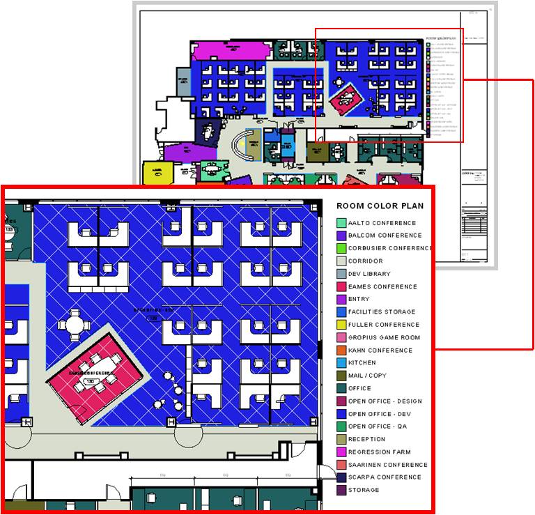
Color Fills
Color Fill enhancements provide better control over the creation, management and display of color fill patterns. Because the software offers more options for conveying design ideas in plan, Revit families such as furniture, equipment, and floors no longer hide behind color fills. Maximizing valuable drawing real estate, the color fill legend reports only those color fills represented in the active view.


Revit Groups
Revit Groups, also known as repeating units, provide a modular design technique ideal for building types comprising of many rooms of similar size, shape, or configuration; such as, hospitals, hotels and apartment buildings. New workflow enhancements include the ability to load an RVT file as a group, save a group as an RVT, or change a group to a linked file. Additional enhancements include a new Group Edit Mode, which provides for the creation of elements while editing a group, numerous user interaction improvements, and the ability to exclude elements on an instance basis to accommodate special conditions.


Dependent Views

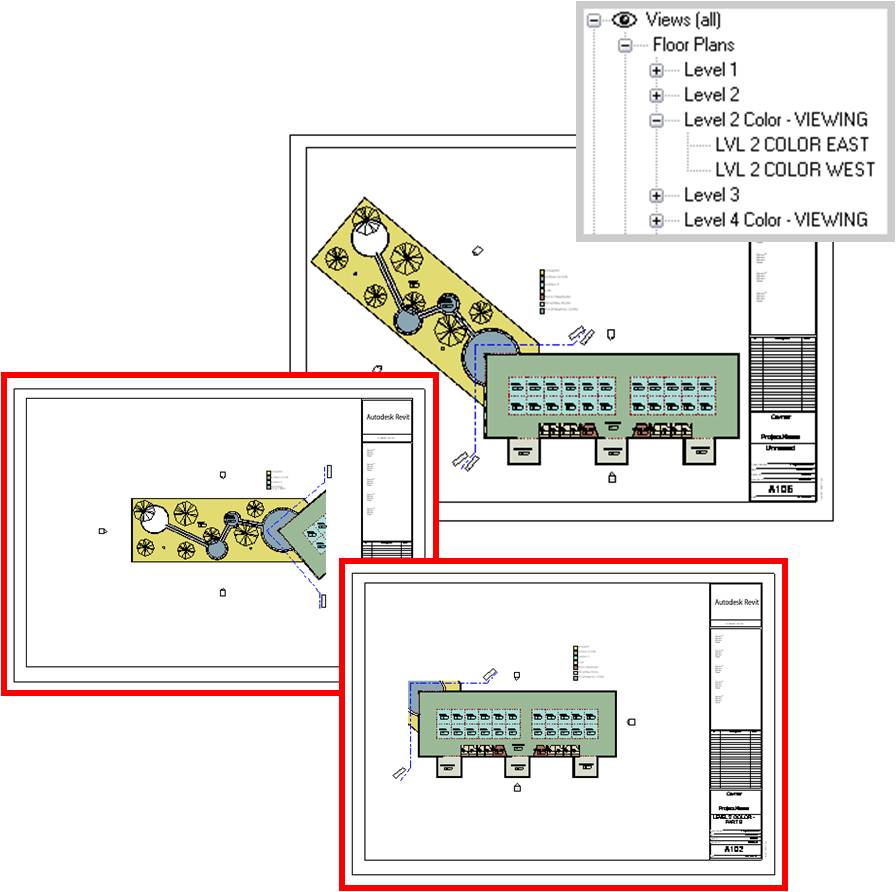
Addressing the needs of firms managing large projects, dependent views provide a robust mechanism for segmenting projects across multiple sheet views. Coordination across sheets is automatically maintained between parent and dependant views helping to ensure model fidelity. All building information, including annotations, is kept accurate and up-to-date throughout the design process.


Match Lines & View References
The addition of Dependent views bring about the creation of new tools in order to support that documentation technique. An additional crop region called the Annotation Crop provides the ability to crop annotations in the view and is accessible from the view properties; Match Lines have been introduced to denote the boundary between two (or more) dependent views; View Reference is a new annotation that provides an associative connection from a parent view to a dependent view. Similar to section heads, the View Reference will automatically display a view’s number and sheet number once the dependent view is placed onto a sheet.

Masking Regions
History of Project: Prior to Revit Architecture 2008, Filled Regions were used, not only as intended, but also as a tool for obscuring or masking model geometry while detailing. The creation of a new Masking Region provides a tool with explicit masking functionality.

Benefit to User: The Masking Region tool provides a new method that is tailored for obscuring other elements. Masking Regions can be used in 2D model views as well as any 2D or 3D Revit Family (including detail elements and annotations).

With the new Masking Regions comes enhanced collaboration between Revit Architecture and AutoCAD. When viewed in DWG format, visual fidelity is maintained as Masking Regions obscure geometry beyond and appear opaque.


Autodesk VIZ and Autodesk 3ds Max Interoperability
Autodesk® VIZ or Autodesk® 3ds Max® software products can import or link 3D DWG™ files produced with Revit Architecture. Maximize your workflow by sharing model geometry, materials, and camera positions throughout the iterative design process. Create stunning photorealistic interior and exterior renderings to help sell your design ideas.

Graphical Overrides
Graphic overrides provide an ability to modify the graphic representation for a single element, thereby offering additional options for how elements appear in views. Graphic overrides also provide a visual method for hiding or revealing single elements or groups of elements by view. Settings are visually retained from session to session, reducing setup time in anticipation of plotting and printing.

File Linking

Offering more flexibility and easier management of linked model information, Revit links are organized within the project browser to provide new drag-and-drop management, together with quick and easy access to the Link Manager. Project visibility is significantly improved for the project team by displaying nested links within host files. The functionality of color fills is also enhanced as fills within host files are applied in linked views.

Tis the Season - AutoCAD Architecture 2008 New Features

It's my favorite time of year... right up there with Christmas! Here are some of the features that will be available in the upcoming AutoCAD Architecture 2008 release.

Area Documentation
  • Space Layout Productivity
In AutoCAD Architecture, the ability to generate spaces automatically from objects & linework has been integrated directly into Palettes. This also provides the advantage of pre-specifying various options, such as style, to help streamline space creation.
  • Automatic Update during design
Spaces in AutoCAD Architecture now are capable of being associative to the objects (walls, slabs, curtain walls, etc) which surround them, eliminating tedious steps of updating space objects when boundaries change. This interaction with bounding objects is also supported through xrefs.

Detail Documentation
  • Master Format 2004 Support
Many users are beginning to use the updated MasterFormat 2004 edition on their building design and construction projects. AutoCAD Architecture now provides content, detail components and keynote databases that are configured for The Construction Specifications InstituteÂ’s MasterFormat 2004.

Annotation Editing
  • Annotative Scaling
Automatic scaling of drawing production allows users to simply change the scale of the design, and the annotations including dimensions, tags and leaders are automatically updated.


Graphic Editing
  • Object Graphic Control
The new Display tab in the Properties Palette provides instant visual feedback after modification of an object or its components. This reduces the steps need to change graphic appearance by leveraging a similar interaction with basic AutoCAD linework.


  • Graphic Control per Viewport
You can also display objects differently in selected layout viewports while retaining their original layer properties in model space and in other layout viewports. With layer property overrides, you no longer need to use tedious and error-prone methods such as duplicating geometry on separate layers or making copies of xrefs. Instead, you can use the Layer Properties Manager to set overrides for color, linetype, lineweight, and plot style for each layout viewport.

Drawing Management
  • Sheets graphics coordinated with views
By selecting an option in the Project Setup dialog, changes in a View drawingÂ’s layer display carry over to its corresponding Sheet View layer display. The Sheet View layer states will resolve to and display the same as the layer states in the View drawing.
  • Launch Projects via shortcuts
You can now launch a Project Navigator project by double clicking on the .APJ file from within Windows Explorer or a shortcut created on you desktop.
  • General Fit and Finish
· Performance
· Project name on Project Navigator
· Add folder in Project Browser
· Better handling of missing templates

Revision Communication
  • Drawing Compare
New Drawing Compare feature, available through the Autodesk Subscription program, uses color-coded displays to show items on a drawing that have been changed, added or deleted by other members of the design team. Changes to items such as styles, fire ratings or other non-graphical properties also can be tracked.

Monday, February 12, 2007

Say Goodbye to ADT

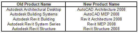
It's been rumored for years. Will Autodesk kill Architectural Desktop? Well, they have finally done it. Architectural Desktop will not be released in the new 2008 line of products. You will have to get used to calling it by its new name-- AutoCAD Architecture 2008. That's right, it's just a name change with some features that are really cool. Autodesk will be releasing their new 2008 product line soon, and one of the biggest changes that the Building Solution Division needs to get used to are the name changes. Below is a summary of the name changes for the 2008 releases.

In the upcoming weeks I will give sneak peeks of some of the new features in the 2008 product lines. Stay tuned.

Thursday, February 01, 2007

Is DEMO a Phase?

This morning I got a chance to read Steve's blog at Revit OpEd. He had a good article on how to show future phases by overlaying them onto sheet views. If you have not seen his blog, check it out. I want to expand on his article by explaining how to set up phases in your project, and defining the terminology for creating phases and filter states.

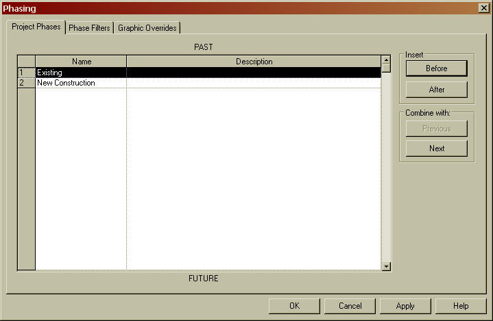
To begin setting up phases, you will find Phasing under the Settings pulldown menu. The dialog box is divided up into tabs. The first tab is where you set up the names of your phases. You will notice that the dialog box has Past on the top and Future on the bottom. It is important to order your phases chronologically. The default template comes with two default phases-- Existing and New Construction. You can rename the defaults or add new phases by clicking on the Before or After buttons in the Insert section.


Most people, including myself, think that Demolition is a phase in a project. With Revit, it is a Phase Status. Let me explain. You could have demolition in any or all phases of your project. It is just part of that particular phase. There are 4 default phase status' that can be used on every phase. You can set items to either Demolished, Existing, New, or Temporary in each phase. The following chart defines each of the phase states.


These settings can be applied in the Properties of each item. Simply tell Revit what phase the item is created in and what phase the item will be demolished in.


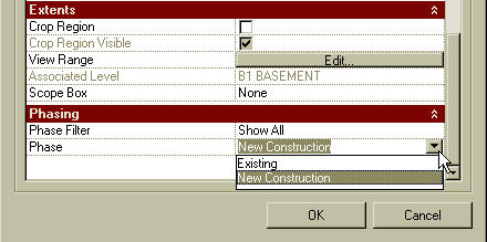
Once you have items set to the correct status, you will need to assign views to show the phase and apply the appropriate phase filter. You can do this in the View Properties.


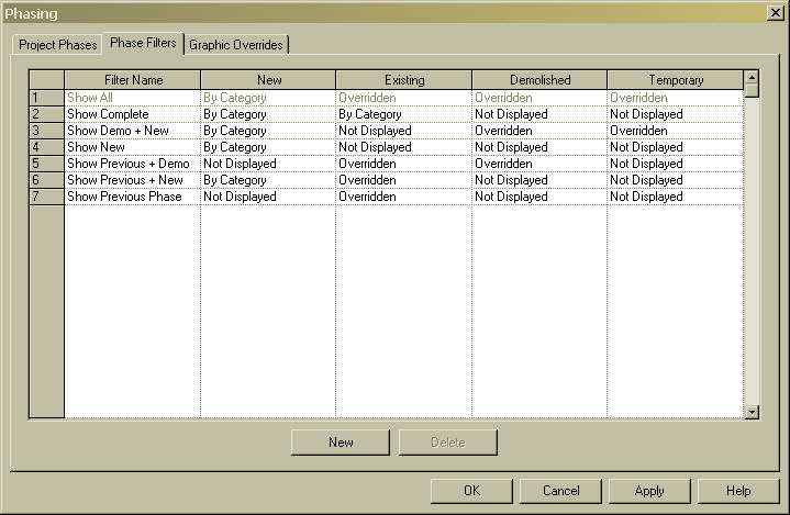
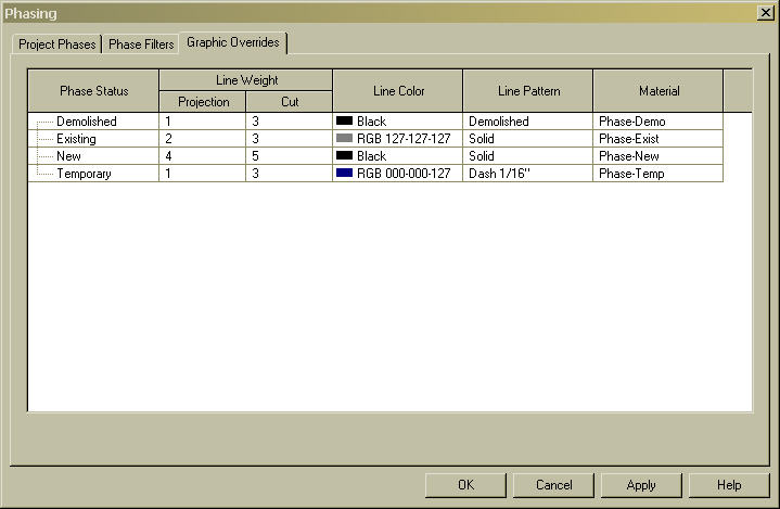
You can create additional Phase Filters or Override the Graphics in the main Phase dialog box under the Settings pulldown.


I hope this helps expand on what Steve wrote about. Phasing in Revit works well if you understand the concept of phases, phase states, and how to apply them to views.

Monday, January 29, 2007

CAD Shack

Todd Shackelford recently acknowledged my blog and I wanted to return the favor. Todd has an excellent blog site where he focuses on the MEP side by using Autodesk Building Systems and Revit Systems. Check out his blog at CAD Shack. Thanks Todd, and keep up the good work!

Wednesday, January 10, 2007

Not Worrying About What You Don't Know

Well, my absence from blogging is over. I had a very nice Christmas season, and I am looking forward to a new year of blogging.

With a post title like this, I could go several directions. I could use this title to discuss the fear people have about switching over to the Revit Platform. After all, change can be a very big issue for some people. But this is not the direction I am heading. I could use this title to discuss how easy it is to gain a basic understanding of the Revit tools. How the tools work the way they ought to work, even if you don't know how to use them. But this is not the direction I am headed either. Okay, as we tell my father-in-law when he is telling us a story and he gets off subject... enough fluff!

I want to use this post to discuss the most common mistake people make when working on a Revit project. That is worrying about the details before it is time to worry about the details. Revit is a modeling program. Most people tend to want to be as accurate as possible, and show as much detail as they can to "wow" their customers with 3D perspectives. I am here to tell you, that if you spend too much time worrying about specific details in the design phase, then you are missing the point.

You should use Revit as a design tool. When I am in a design stage of a project, I don't care what size the column needs to be or what the exact make-up of the exterior walls are. I just want to focus on the design intent and make sure that the spaces work. As CAD drafters, we sometimes get too caught up in the details too early in the game.

Let me introduce a new Revit term to you. It's called Space Holders. You can use space holders to quickly block out something in your model that you will eventually go back and revise to the correct component. This will allow you to keep focused on the design, not the details. For example, when laying out a building, I know that I will have to have columns in my building, but I may not know where, what type, or the exact size of the column until later in the game. Typically, we give our structural engineers a base plan and they provide us with the column spacing and sizes. So in the early stages, I may just want to use a standard box column in my plans as a preliminary column spacing plan. After my engineer designs the structural model, I can simply exchange my place holder columns with the correctly sized columns by replacing the family. This will save me time and frustration in the design phase.

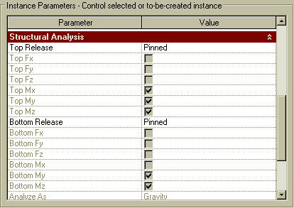
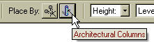
While I am on the subject of columns, let me take the time to tell you the difference between Architectural columns and Structural columns in Revit. The architectural column is found on the Modeling Design Bar while the structural column is found on the Structural Design Bar. They work and feel basically the same. The only difference between the two is that the structural columns have additional parameters that the engineer can use to extract to his structural design program to size the member. These parameters will be grayed out unless you are running Revit Structural.
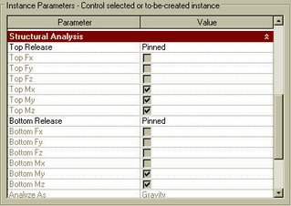

If you are working with an engineer that is using Revit, then by all means, use structural columns as opposed to architectural columns. If your engineer is not using Revit, then it really doesn't matter. You can use architectural columns as wrap arounds and structural columns as the actual column. If you are doing this, then when placing the structural columns, you can insert them by selecting your architectural column wrap arounds as the mode of inserting.
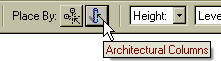
This will save time and insure that your columns and the structural columns are connected. If one moves, the other will move with it. Pretty neat trick to make sure your wrap arounds are in the correct location.

Enough fluff! Back to my original post title. To sum it up, don't get caught up in the details too early in the game. Use place holders when needed, and just make sure that you eventually go back and replace the place holders with the correct components when that knowledge is gained.

Wednesday, December 06, 2006

Revisions in Revit

The way Revit handles revisions works very well. I will walk you through the simple steps in managing revisions for a project.

The first step is to open the Revision Setting dialog box. Expand the Settings pulldown and select Revision to open the dialog box.


The first settings will control whether your revision numbers are By Project or By Sheet. This will depend on your company standards. By project will tag your revision with the delta symbol of the next available number. By sheet will tag your revision with the delta symbol of the next number of that particular sheet. You should set this at the beginning and leave it as your default.

The Revision Table begins with one revision as the default. You can edit the Release Date, Description, check the Issue box, or fill in who the revision was Issued To for any revision. You can add new revisions by clicking on the NEW button.

Once you have a revision issued, you may want to change the visibility so the contractor will not get confused by looking at old revision clouds. You can choose to show either "Cloud and Tag", "Tag", or "None" under the Visible column.


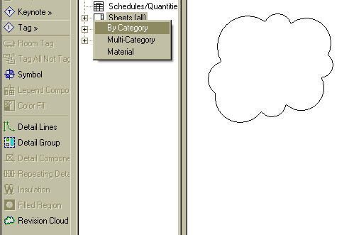
The actual Revision command can be found on the Drafting menu bar. This command is only available in a Sheet View. Once the command is started, you will enter into a sketch mode. Simply draw the cloud around the area that was revised and click Finish Sketch. You can then tag the cloud by starting the Tag command and picking By Category. If the Revision Tag is not loaded into your current project, it can be found under the Annotation folder in your family directory.

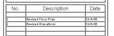
As soon as you place a cloud onto a sheet, the Revision Schedule in the title block will be updated to include the revision number, description, and date. The revision schedule is included on the default template title block.


There is a known bug with release 9.1 that will not allow you to add a revision schedule to a custom title block. Hopefully this will be fixed soon, but for now, you can create your title block by editing the title block on the default template.

Keeping track of your revisions are simple in Revit. It manages all your revision numbers and dates. Of course, hopefully you will not need to know how to use this due to the fact that you never actually have to issue any revisions... right?!?

Friday, November 17, 2006

Making Spaces Work For You - In REVIT

It only makes sense that my first "How To" tip in Revit be on spaces. Especially since the current issue of AUGI World features an article by yours truly on Making Spaces Work For You in ADT.

Spaces in Revit are called Rooms. They work similarly to ADT with a few exceptions. Rooms in Revit define the use of the space. They are simple enough to define. You begin by clicking on Room on the Basic tab of the Design Bar. Then as you roll over your plan you will see the room limits highlighted by enclosed walls. On the Options bar you have the option to place the Room Tag as you are defining the rooms. You also have options to set the upper limits of the room, the rotation of the tag, and naming the room.


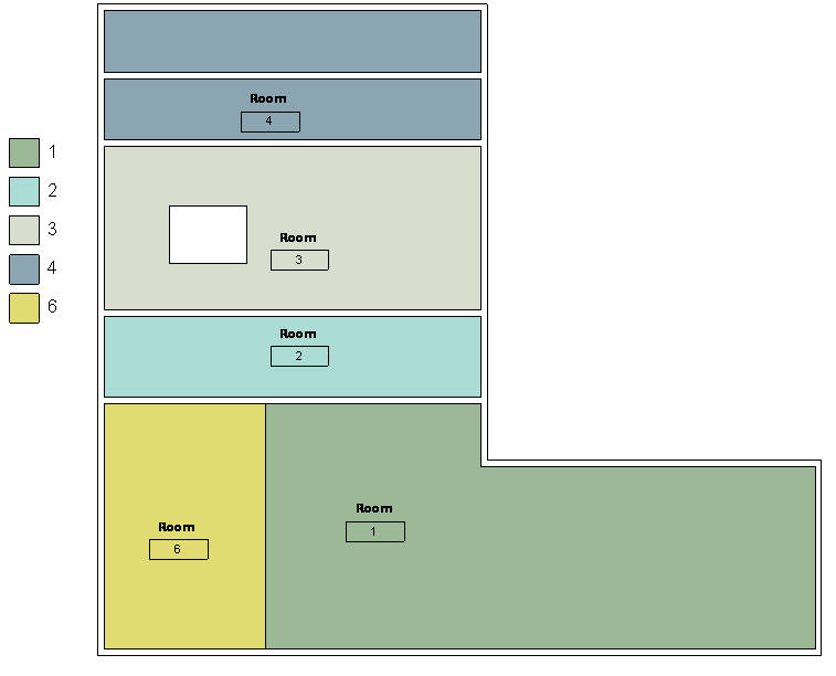
Once the rooms are defined, you have a couple of additional options to define the extents of each room. First, on the Room and Area tab of the design bar, you can use the Room Separation tool to draw lines to define the extents of the room. This is useful when you have an open area that is divided up into separate spaces. As you draw room separations, the rooms that are already defined will be updated to extend to the room separation lines. The area outside of the room separation line will not be part of any rooms. You can use the Room tool to define the new room that was created by the room separation tool. So like ADT, you can use either walls or lines to define the extents of your rooms.

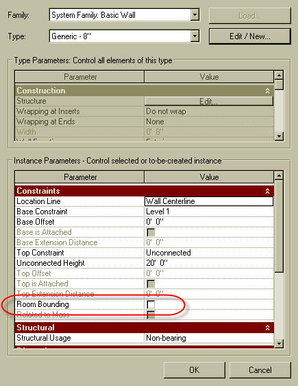
You also have the ability to select on an individual wall and go into the properties to tell it not to use this particular wall as a room boundary. This will be useful when working on a restroom with toilet stalls. You will want to set the toilet partitions not to act as a room boundary. Simply uncheck the box in the options dialog box next to Room Bounding. If you make this change after the spaces are created you will get a warning dialog box because you will have two spaces that will be overlapping each other. In the warning dialog box click on Delete Rooms and one room will be deleted, leaving the new combined room.


Rooms can be used to create schedules like square footage schedules or room finish schedules. You can also use Color Fills to create a colored floor plan for a graphical representation of the room extents.

Rooms are similar to Spaces in ADT. They contain the information of the Room. With rooms you can define usage, finish materials, calculate square footage or volume information, or simply use them to insert your room tags.

Wednesday, November 08, 2006

Move over ADT... Make room for Revit

I have had some time this week to dive deep into Revit. I was hesitant in the beginning like many are, but I just finished my first project. As an ADT user for years, I found Revit fairly easy to pick up as long as I kept one thought in mind-- forget what you know about CAD. I know that goes against the name of this blog, but it is necessary to understand how Revit works. I have been promising people that I would extend this blog to include Revit, and now is the time.

The basic commands in Revit work similarly to ADT. The walls clean up when joined, doors and windows can be inserted into walls, and there is a line command that you can use by picking a start point and an end point. That, however, is where the similarities end.

I was serious when I said to forget what you know about CAD. I forced myself to do this as I was learning this program. When I caught myself trying to do something in the way I would in ADT, I quickly became frustrated. I believe if I had never learned ADT, I would have been able to pick Revit up without a hitch. Once I got into it, I started enjoying it more and more. Looking back at my first project, although it was small, I can see how you can make design decisions at an early stage and see the effects of that decision in multiple views.

In the past I have had the attitude of, "well, ADT can do that too." Yes, ADT can do much of what Revit does. But you have to work to make it do it. The coordination of drawings, or views as Revit calls them, is what impressed me the most. I never had to worry about updating xrefs or schedules, or about making sure that I had the right callout on my elevations.

I do not want to run any of my ADT users away. I will continue writing about ADT, but expect to see me writing more and more about Revit.

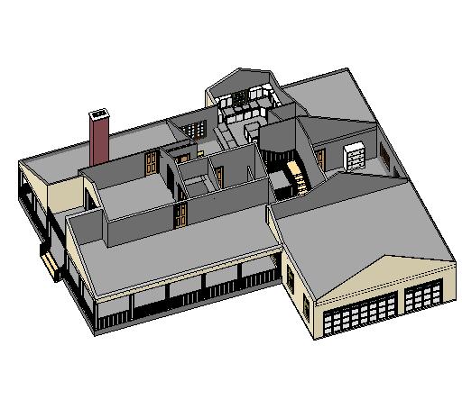
Below are several images of my first Revit project. I am impressed, even if nobody else is.


Thursday, October 19, 2006

Successful CAD Camp

Alacad hosted CAD Camp in Birmingham this week. I hope the ones that attended walked away with a greater knowledge of AutoDesk products. I feel like it was a huge success, but being on the presenting side of the table sometimes muddies the water. I presented two classes, both ADT related-- one on Spaces and the other on AEC Dimensions. Both classes received good feedback. If you were not able to attend, be sure to check out the next issue of AUGI World. You will find an article of mine on Spaces.

I also sat in on a Product Migration Roundtable hosted by Robert Green. This was a useful discussion of how to get new products implemented inside of your company. Robert did a good job on leading the discussion about what we have seen work, and what has not worked in implementation. I recently returned from Chicago where I attended ICE (Implementation Certified Expert) training. I will be sharing some of the information that I learned in the next few weeks here in my blog. The training class was intense, but I was able to pass the test to certify me as an expert. Without getting into too many details for now, just keep in mind that implementation does not equal training. Training is only a small part of a successful implementation. Watch for more information on implementation in coming blogs.

By the way... we will be hosting another CAD camp in Nashville on January 18, 2007. Watch this link AUGI CAD Camp for registration info to be posted soon.

Wednesday, September 27, 2006

ADT SP1 is Available!

SP1 for ADT 2007 has been posted. I am in the process of installing it now. I've read the readme file, and it looks like it has corrected many of the little bugs inside the program. Here is the link to download the service patch. ADT SP1

Monday, September 25, 2006

A.U. Connect

Autodesk University is coming! I am excited about this year's A.U. I am all signed up and ready to go to this great event. My excitement grew this week as the A.U. website launched A.U. Connect. This is a great place to see who is coming and who is similar to your personality and likes. If you haven't registered yet for A.U., get with it and sign up. The classes are filling up fast. If you are registered, then log into A.U. connect and enter your profile information. It is fun to see who is similar to you and where they are from.

Wednesday, September 06, 2006

Using Lists in ADT 2007

One of the most unnoticed features in 2007 is the ability to create lists. These lists can be used to help your CADD standards. As an ex-CADD manager, I despised reviewing a set of drawings when I found the same term used over and over, but with different call outs. For example, calling out Gypsum Board in one set of drawings, I found it listed as gyp. bd, GYP. Board, Gypsum, US Gyp, Drywall, and of course, gypsum board. Calling out the same material with so many terms will lead the contractor to confusion or R.F.I.'s. The ability to create lists will enable your users to pick from a pulldown menu the name of the material so it is coordinated and never misspelled.

To create a list, go to Style Manager. You will see List Definitions under Multi-Purpose Objects. You can create a new one or modify an existing one. They are styles, and like every other style, they must be loaded into your current drawing to be used. In creating a list definition, there are two main tabs that need to be looked at. The Applies To tab is critical to assign what this list will be used for. You will see three(3) options listed: Manual Property Definition, Space Names, and Zone Names.

Manual Property Definition should be selected if you intend to use this list on any property set definition. Once this is selected, you have the option to change the type of a manual property set definition from Text to List in the Definition tab of the property set. The following example has a list created and assigned to the door frame material. The list gives the users the option to pick metal, wood, or aluminum.

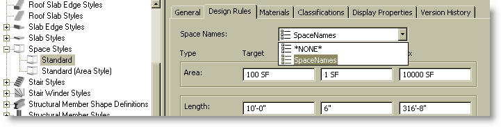
The other two Applies To options in the List definitions will enable the list to be used as either Space Names or Zone Names. This is a great way to ensure that Room Names are spelled correctly. To have your room tag pull the name from the space name, set this up on your MV room tag block. To use this list as space names you need to assign the Space Names of the space style to the list in the Design tab of the space style.

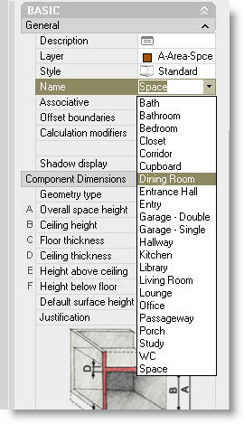
This example shows a residential list of space names that the room tag is pulling from to name the room.The Items tab in the list definitions is where you actually create the lists. It is fairly straight forward. Simply pick Add and type in the name of the item.

Lists can be created in templates so they are always loaded into your current drawings. Being able to pick a list, as opposed to typing it in, will increase productivity and decrease inconsistency and spelling mistakes.